8.0 Model Execution
The “Run” menu validates the model parameters, generates the data set, and launches the model simulation.
8.1 Validate
The “Validate” function in the “Run” drop-down menu checks all the model inputs before model files are created. Selecting “Validate” from the “Run” drop-down menu opens the “Validate Model” dialog box, which has two tabs: “General” and “Extend.” On the “General” tab (Figure 8.1), general information about the model is displayed, such as the number of nodes and elements.
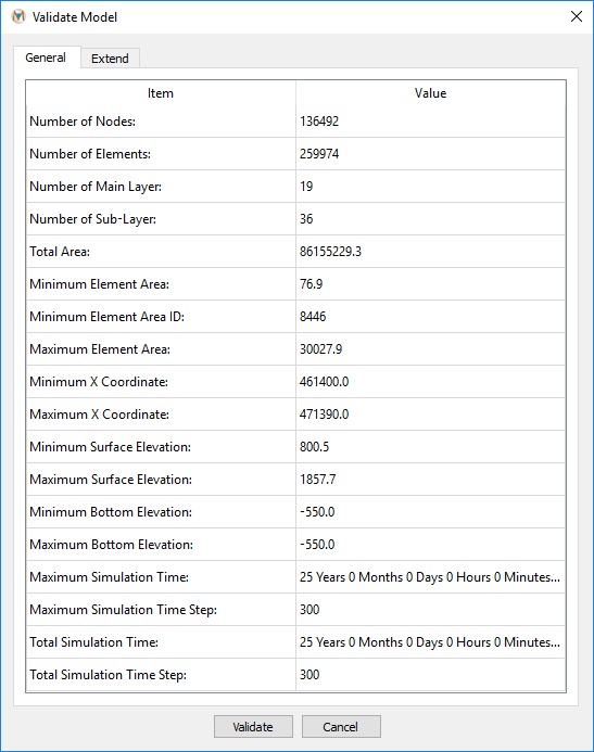
Figure 8.1 The “General” tab in the “Validate Model” dialog box
The “Extend” tab (Figure 8.2) contains additional information about the model, such as boundary conditions and mining information. Reviewing the information on both of these tabs is strongly recommended to ensure that the model has been defined correctly.
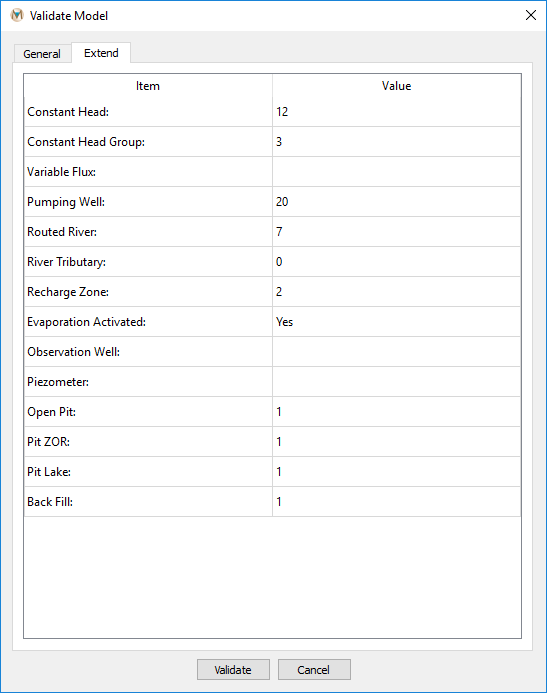
Figure 8.2 The “Extend” tab in the “Validate Model” dialog box
Clicking the “Validate” button at the bottom of the dialog box checks all the inputs to the model. If there is an error in an input, then it is listed in red in a pop-up window; if not, then no errors are listed (Figure 8.3). The user is advised to fix all errors prior to running the model. If there are no errors, then the model is ready for the simulation. Click “OK” to close the “Validate Model” dialog box.
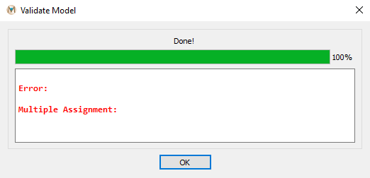
Figure 8.3 A completed model validation
8.2 Create Data Set
To create the data set for a model run, select “Create Data Set” from the “Run” drop-down menu. The “Choose a Simulation Directory” window opens. Choose a folder to store all the input files created and then click the “Select Folder” button.
Entering input to the numerical portion of MINEDW is accomplished by reading model-input files that define the groundwater problem to be simulated. Depending on the complexity of the problem, as many as 18 input files are necessary to run a MINEDW model simulation. For relatively simple problems, many of the files contain a zero, indicating that the input for that part of the simulation does not apply. The MINEDW program uses the files listed below for performing simulations.
CHEAD.DAT — File containing constant-head conditions information.
ELM.FEM — File containing finite-element mesh incidences.
ELEMENTK.DAT — File containing elements that change hydraulic parameters over time.
EVAP.DAT — File containing evapotranspiration package input.
FAULT.DAT — File containing fault internal conditions information (file defining where nodes are “linked” to simulate hydraulic connection).
FILE.FEL — Lists all of the input files used for the simulation.
FLUX.DAT — File containing variable-boundary conditions information.
KFILE.DAT — File containing aquifer properties for different hydrogeologic zones.
MINING.DAT — File containing pit-plan data.
MODEL.DAT — Main input file containing simulation parameters, output controls, grid, and solver parameters.
NODE.FEM — File containing finite-element mesh (nodes) coordinates.
PARA.FEM — File containing hydrogeologic-zone specifications.
PUMP.DAT — File containing pumping data that define where, when, and how much pumping is simulated.
PUMPWELLS.DAT — File containing pumping-well information such as node number, number of pump, screen interval, and pumping time-series data (rate and date).
RECHARGE.DAT — File containing recharge package input.
RIVER.DAT — File containing river package input.
TIMESTEP.DAT — File containing time-step length information.
WATERLEVEL.DAT — File containing initial water-level data.
8.3 Execute
To run the simulation, select “Execute” from the “Run” drop-down menu on the Main Menu banner at the top of the screen. The “Choose a Working Directory” window opens. Choose the folder containing the input files and click “Select Folder.” A window like that shown in Figure 8.4 opens. The simulation’s progress is shown at the top of the window. Any errors that are not fatal are displayed in red in the progress window on the left. The file “MINEDW.ERR” can also be reviewed after each model run to view any errors. The “Abort” button will terminate the simulation, while the “Output Current Result” button will print the current simulation results to the appropriate output files.
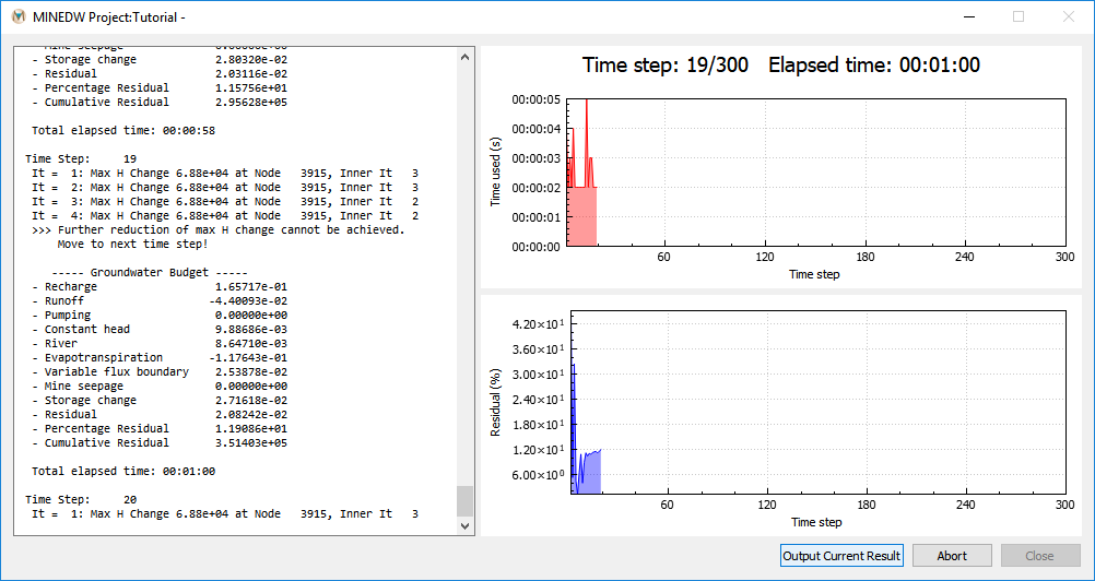
Figure 8.4. Screen display of output from the model run